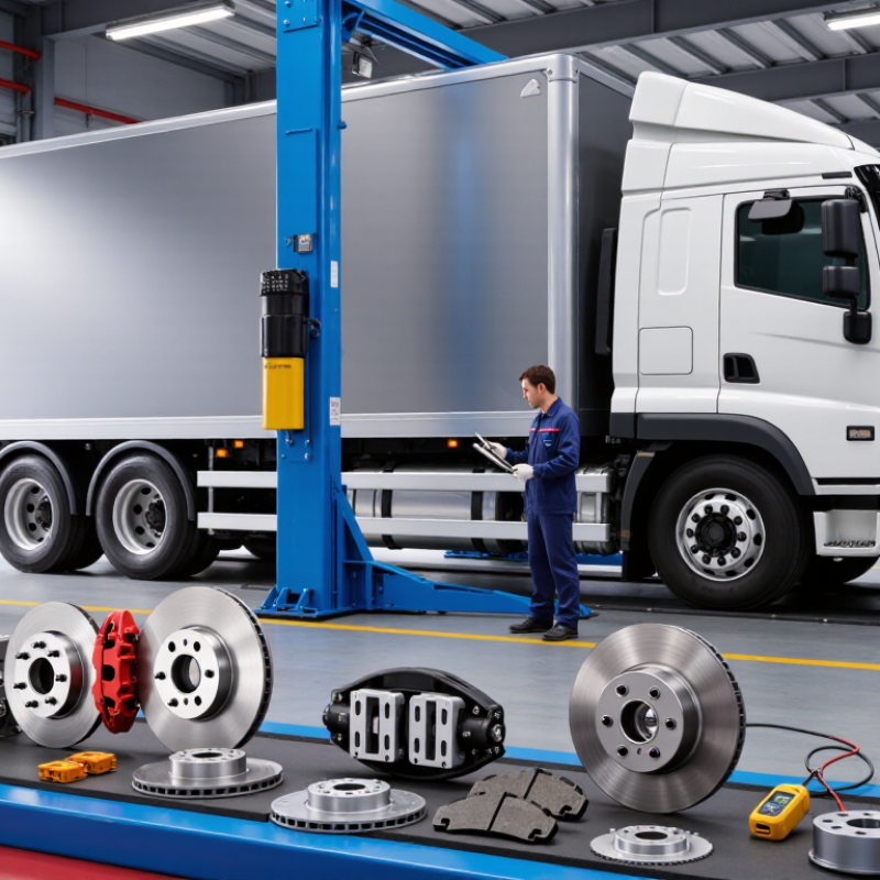
Choosing brake components for a commercial vehicle is not a simple parts-list exercise. Fleet safety, payload, road conditions, and maintenance capacity all shape the decision. This guide explains how to choose brake components for commercial vehicles through practical, evidence-based reasoning. It focuses on brake pads, shoes, rotors, drums, calipers, chambers, valves, and related hardware.
A delivery van making frequent urban stops needs different priorities from a loaded tractor-trailer crossing mountain routes. Heat, dust, water, corrosion, and repeated braking can change component performance. Start with the vehicle manufacturer’s specifications, axle ratings, approved part numbers, and service history. Then compare friction ratings, thermal capacity, wear behavior, fitment, and supplier traceability. A component that fits physically may still perform poorly under the vehicle’s real workload.
Small details matter. A worn chamber pushrod, contaminated lining, or incorrectly adjusted system can undermine new parts. Technicians should inspect the complete braking system, follow current service procedures, and document measurements before replacement. Independent testing and reputable technical standards offer useful checks, although no source replaces a qualified inspection. Even experienced teams can miss a pattern when records are incomplete. That weakness deserves attention. This article presents a careful framework for safer, more consistent choices, while recognizing that conditions differ across fleets. The best decision balances verified compatibility, lifecycle cost, braking performance, and realistic maintenance support—not the lowest purchase price.
Choosing brake components for a commercial vehicle starts with its real duty cycle, not its brochure specifications. GVWR is the maximum loaded vehicle weight, including passengers, cargo, and equipment. GAWR defines the permitted load on each axle. These values reveal how much braking energy each axle may handle.
A delivery truck at 80% load behaves differently from a fully loaded vehicle on a long descent. Record typical cargo weight, stop frequency, road grades, traffic speed, and ambient temperature. Then examine front and rear axle loading separately. Brake rotors, drums, calipers, pads, and linings need suitable thermal capacity for that pattern. A larger component is not automatically better. It may increase weight, cost, or maintenance difficulty.
A 60 mph test provides a useful reference point. Measure stopping distance, pedal effort, rotor temperature, and wheel behavior under controlled loading. Repeat the stops to expose fade. Include the intended GVWR condition, not only an unloaded vehicle. Surface grip, tire condition, brake balance, and driver input can change the result. One clean stop proves very little. A test on level pavement also cannot represent a mountain route. That limitation matters. In field evaluations, teams sometimes select components from the first successful stop. I consider that a weak decision. Review temperature recovery, lining wear, and repeated-stop performance before approving the design. Recheck GAWR after adding cargo equipment, because a small axle overload can distort the entire brake assessment.
At a constant test speed of 60 mph, braking energy increases directly with vehicle mass. The chart uses representative commercial-vehicle duty-cycle cases and calculates kinetic energy using E = ½mv², where 60 mph equals 26.82 m/s. GVWR indicates the maximum loaded vehicle mass, while front and rear GAWR values describe the permitted load on each axle group. Higher energy demand generally requires greater brake thermal capacity and more robust component selection.
Choosing brake components for commercial vehicles starts with axle load, not catalog fitment. Each axle carries a different share of the vehicle’s gross weight. Select calipers, drums, rotors, chambers, and linings for the axle’s rated load and expected heat exposure. The system must also work with the vehicle’s tires, suspension, ABS, and brake balance.
FMVSS No. 121 requires applicable air-braked vehicles to stop within 250 feet from 60 mph under specified test conditions. Treat that distance as a compliance threshold, not a comfortable design target. Real roads add slopes, rain, worn tires, uneven loading, and delayed maintenance. The Commercial Vehicle Safety Alliance reported an 18.1% out-of-service rate during Brake Safety Week 2023, covering 18,875 inspected vehicles. That figure shows how quickly small brake defects become operational risks.
Tips: Measure actual axle weights before selecting components. Check brake torque against the heaviest axle load. Confirm temperature ratings for downhill routes and repeated stops. Inspect chamber stroke, lining thickness, rotor condition, and tire pressure together. I have seen teams trust physical fitment too much. That shortcut can hide poor brake balance. Recheck calculations after payload or axle placement changes. A perfect test result can still weaken in service.
Choosing an air-brake chamber starts with its SAE size: 9, 12, 16, 20, 24, 30, or 36. The number represents nominal diaphragm area in square inches. At the same air pressure, a larger chamber produces greater pushrod force. However, force alone does not select the correct part. Axle loading, drum or disc design, slack-adjuster length, stroke, and available mounting space also matter. SAE J231 and FMVSS No. 121 provide important performance and identification guidance.
For example, sizes 9 to 20 often suit lighter service-brake applications. Sizes 24, 30, and 36 are common on heavier axles and spring-brake assemblies. A size 30 chamber may deliver more force than a size 24, but excessive force can increase lining wear or affect balance. It can also create insufficient stroke clearance. CVSA’s 2024 International Roadcheck reported that roughly one in five inspected commercial vehicles received an out-of-service order. Brake-system defects remained among the recurring inspection concerns. That finding supports careful chamber matching, not simple upsizing.
Tips: Confirm the vehicle maker’s chamber size, stroke, and mounting specification before ordering. Measure pushrod travel with the brakes released and applied. Check the slack adjuster angle at full stroke. Do not mix service and spring sections casually. I have seen “bigger is safer” fail in practice. The better question is whether the chamber delivers the required force within the approved stroke range. Record air pressure, adjustment, and wheel-end condition during installation. A rushed measurement can invalidate an otherwise correct selection.
Brake components for commercial vehicles must resist heat, carry heavy loads, and support dependable stopping. Linings and rotors should be selected together, not as isolated parts. A lining with stable friction at high temperature can reduce fade during repeated downhill braking. However, an aggressive friction material may increase rotor wear or create noise.
Review axle loads, trailer use, road grades, and braking frequency before choosing components. Rotor thickness, ventilation, metallurgy, and heat capacity also matter. In practical inspections, uneven rotor wear often reveals poor bedding, caliper problems, or incorrect lining compatibility. Measure temperatures and wear patterns when possible. Laboratory ratings alone cannot represent every operating route. That is worth remembering.
Tips: Confirm that the complete air-brake system meets FMVSS 121 requirements through qualified engineering review and documented testing. Check pushrod travel, air pressure, brake balance, and stopping performance after installation. Follow the supplier’s bedding procedure, then inspect for cracks, hot spots, glazing, and uneven contact. A compliant component can still perform poorly if installation is careless. Temperature paint or infrared readings can provide useful evidence during fleet trials. Do not ignore payload changes. A vehicle running lightly today may operate fully loaded tomorrow.
Verify ABS performance before comparing prices or lining materials. A component that feels strong in a workshop may behave differently under a loaded vehicle. Check ABS fault records, wheel-speed sensor signals, and modulation during repeated stops. Test both empty and fully loaded conditions. Include wet pavement and split-friction surfaces where possible. Short stops matter.
Brake balance deserves equal attention. Compare left-to-right braking force, front-to-rear distribution, and axle loading. Excessive rear braking can cause instability, while weak rear braking increases front-axle heat.
Record pedal pressure, vehicle speed, brake temperature, and stopping distance. Small temperature differences can reveal uneven contact. Do not trust one impressive result.
When a supplier provides SAE J2114 test results, request the exact revision and test scope. Confirm the vehicle mass, tire condition, brake temperature, test speed, pressure, and environmental conditions. Check whether results came from a complete system or one component.
Repeatability is more useful than a single peak value. A clean chart can still hide poor test control. That is where reviews often fail.
Recheck the raw data, equipment calibration, and failure criteria. If the report omits these details, treat its conclusions carefully. The safest choice is the component supported by traceable testing, balanced braking behavior, and ABS performance across realistic operating conditions.
GVWR is the vehicle’s maximum loaded weight. GAWR limits the load on each axle. These values show how much braking energy each axle may handle. A small axle overload can distort the entire assessment.
Record typical cargo weight, stop frequency, road grades, speed, and ambient temperature. Include delivery routes, traffic conditions, and long downhill sections. A lightly loaded truck behaves differently. That difference matters.
Measure stopping distance, pedal effort, rotor temperature, and wheel behavior. Test the vehicle under its intended loaded condition. Repeat the stops to reveal brake fade. One clean stop proves very little.
Repeated braking can raise rotor temperatures quickly. High heat may reduce friction and increase stopping distance. Check temperature recovery, lining wear, and contact patterns. A level-road test cannot represent every mountain route.
Common chamber sizes include 9, 12, 16, 20, 24, 30, and 36. The number indicates nominal diaphragm area in square inches. At equal air pressure, a larger chamber usually creates more pushrod force. More force is not automatically safer.
Confirm chamber size, stroke, mounting space, axle load, and slack-adjuster length. Measure pushrod travel with the brakes released and applied. Check the slack-adjuster angle at full stroke. A rushed measurement can invalidate the selection.
Select linings and rotors as a matched system. Stable friction at high temperature can reduce repeated-stop fade. Aggressive friction material may increase rotor wear or noise. Compatibility matters more than a single laboratory rating.
Check air pressure, pushrod travel, brake balance, and stopping performance. Follow the bedding procedure carefully. Inspect for cracks, hot spots, glazing, and uneven contact. I would not approve the design after one successful test.
Choosing the right braking system begins with understanding the vehicle’s duty cycle, including its gross vehicle weight rating (GVWR), gross axle weight ratings (GAWR), payload, terrain, speed, and operating frequency. To learn how to choose brake components for commercial vehicles, engineers should match brake capacity to the actual axle loads and confirm that stopping performance meets the 250-foot limit under 60 mph test conditions. Air-brake chambers should be selected according to required force and available clearance, using suitable SAE sizes such as 9, 12, 16, 20, 24, 30, or 36.
The selection should also consider lining and rotor materials that resist heat, wear, and brake fade while supporting FMVSS 121 compliance. Finally, the complete system must be checked for ABS effectiveness, brake balance, and consistent performance through SAE J2114 testing. A properly matched combination improves stopping stability, thermal durability, maintenance planning, and overall commercial vehicle safety.

MOAD AUTO